Membrane Contactor Technology
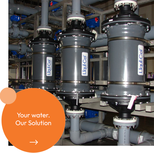
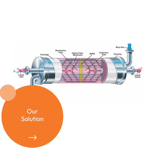
Liqui-Cel® Membrane Contactors make it possible to transfer gas to or from an aqueous stream without dispersion. A membrane contactor can contain thousands of microporous polypropylene hollow fibers knitted into an array that is wound around a center tube. The hollow fibers are arranged with uniform spacing, allowing greater flow capacity and utilization of the total membrane surface area. Because the hollow fiber membrane is hydrophobic, liquids will not penetrate the membrane pores. A higher pressure is applied to the liquid stream relative to the gas stream. Unlike dispersed-phase contactors, such as packed columns, membrane contactors provide a constant interfacial area for transfer over the entire range of flow rates.
We sell products from

Although LiquiCel Membrane Contactors utilize a microporous membrane, the separation principle differs substantially from other membrane separations such as filtration and gas separation. With Liqui-Cel Membrane Contactors there is no convective flow through the pores. Instead, the membrane acts as an inert support that brings the liquid and gas phases into direct contact without dispersion. The transfer between the liquid and gas phases is primarily governed by the partial pressure difference of the target gas species between the two phases.
The degassing surface area per unit volume is an order of magnitude higher than traditional technologies such as packed columns, forced draft deaerators and vacuum towers. This greater surface area to volume ratio leads to a dramatic reduction in system size at a comparable level of performance. LiquiCel Membrane Contactors are mechanical devices that do not require chemicals to operate.
Questions about our products?
Contactor design
Several membrane contactor design variants are available to meet the needs of a broad range of applications and range of flow rates. Each variant is designed to maximize the liquid-gas contact area.
Extra-Flow – uses a central baffle to force liquids radially over the fiber array. Liquid flows on the outside (shell side) of the hollow fibers.
High Pressure – similar to the Extra-Flow with center baffle design, but with a different housing concept for high pressure applications. The 8 x 40 and 8 x 80-inch contactors use this design.
Radial – uses a center tube with no direct outlet to force liquids radially across the fibre array. The 1 x 3 and 2 x 6 SuperPhobic Contactors utilize this design.
MiniModule™ – does not utilise a baffle and the liquid and gas sides are reversed. Liquid flows through the inside of the hollow fiber (lumen side) while a vacuum is applied or a strip gas is used on the outside (shell side) of the hollow fibres.
MicroModule™ – liquid flows into the liquid inlet, crosses the hollow fibers and then exits through the opposite port. No baffle is used. A vacuum or a strip gas can be applied to either gas port.
Membrane Selection
Liqui-Cel Membrane Contactors utilize a variety of membrane fibre types for specific transfer applications.
X40 – Oxygen removal from liquids
X50 – Carbon dioxide removal from liquids
XIND – Industrial liquid degassing
Polyolefin – Low surface tension fluid (20 – 40 dynes/cm)
Operation
Gas Absorption
When using membrane contactors in gas absorption applications a gas is introduced on the inside (lumen side) of the hollow fiber membrane and the liquid phase is introduced to the outside (shell side) of the hollow fibre. The partial pressure of the gas and the water temperature controls the amount of gas dissolved in the liquid phase.
Gas Stripping
When using membrane contactors in gas stripping applications a vacuum or stripping gas, or combination of the two, is applied to the lumen side of the hollow fiber. The liquid stream is introduced to the outside of the fiber. The partial pressure of the target species in the gas phase is decreased to remove dissolved gases from the liquid phase.


Operation modes
A dissolved gas can be removed from an aqueous stream with a membrane contactor using one of four different operating modes:
- Sweep Gas
- Vacuum
- Sweep-Assisted Vacuum (Combo Mode)
- Blower in Suction Mode (Induced Draft Blower) for economical CO2 removal
Sweep Gas Mode
Sweep gas mode is a process by which a gas in the lumen side of the contactor flows counter-current
to the water flow. By choosing a sweep gas that is different from the gas targeted for removal, a partial pressure gradient is created between the liquid phase (shell side) and the gas phase (lumen side). This forces the target gas to transfer to the lumen side and be swept away. The purity of the sweep gas will impact the dissolved gas level that can be achieved at the liquid outlet. Therefore, a minimum of ISO Class 1 air with an oil content of 0.01 mg/m3 or less is recommended. When using the air stripping technique, the liquid stream will become saturated with air. The same principle applies to MiniModule™.
The gas phase, however, is on the shell side of the contactor while the liquid phase is on the lumen side.
Using on-site compressed dry air at temperatures below 30 °C as a sweep gas is a very economical operating mode for removing carbon dioxide from the liquid stream.
Vacuum Mode
Vacuum mode is a process in which a vacuum is applied to the lumen side of the contactor. A vacuum should be drawn from both lumen ports, as opposed to a single lumen port, to improve bulk gas stripping efficiency. When the vacuum is applied, it creates a partial pressure differential between the liquid phase (shell) and the gas phase (lumen). This partial pressure differential drives the transfer of dissolved gases from the shell side to the lumen side. These gases are discharged through the vacuum pump. Vacuum levels affect removal efficiency. The deeper the vacuum, the lower the dissolved gas outlet concentrations will be. The same principle applies to MiniModule™, however, the gas/vacuum phase is on the shell side of the contactor while the liquid phase is on the lumen side.
The vacuum method is recommended for total gas control and bulk dissolved gas removal.
Sweep Assisted Vacuum (Combo Mode)
Sweep-Assisted Vacuum (Combo Mode) is a method in which a sweep gas is introduced to one lumen side port of the contactor, while the other lumen side port is connected to a vacuum source. The sweep gas helps move and dilute the gas that is in the vacuum stream. Typical recommended vacuum level is 50 to 100 mm Hg absolute at sea level.
Sweep-assisted vacuum is the most efficient way to achieve low levels of dissolved oxygen or low levels of carbon dioxide in water.
Blower in Suction Mode (Induced Draft Blower)
Using a blower in suction mode and pulling in atmospheric air is a low cost alternative to using compressed air for carbon dioxide removal. However, it is critical that blower exhaust is piped away from the air intake ports of the contactors. Dissolved CO2 levels down to 5 ppm in water can be achieved using this method. Lower levels of CO2 removal to <1 ppm can be obtained with vacuum and air sweep combo mode.


